1.0Eligible 3D Models
[vc_row_inner][vc_column_inner width=”1/2″]
1.1Photo/Real
The first hurdle for a PixelSquid model is photo realism. The 3D model must be indistinguishable from a photograph of a real-world object when rendered full frame at 2048 x 2048. If the model is intended to represent a real-world object, it must accurately represent that object in proportion, texturing, and appearance. Quality of a model is more than just making a pretty picture. Materials and texture maps must be detailed but also render efficiently. There must be no texture stretching, faceting, visible tiling, or visible symmetry when rendered. The render should not contain visible cloning.
[/vc_column_inner][vc_column_inner width=”1/2″]


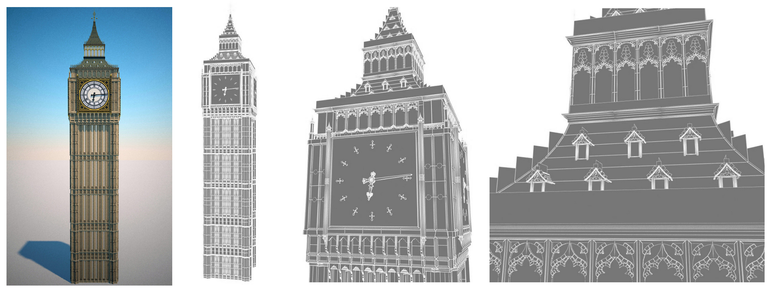
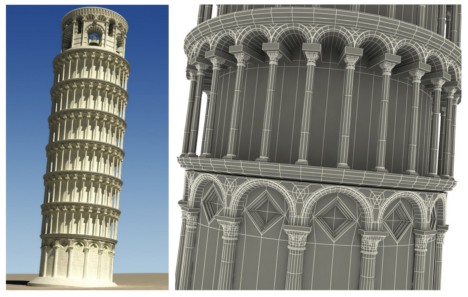
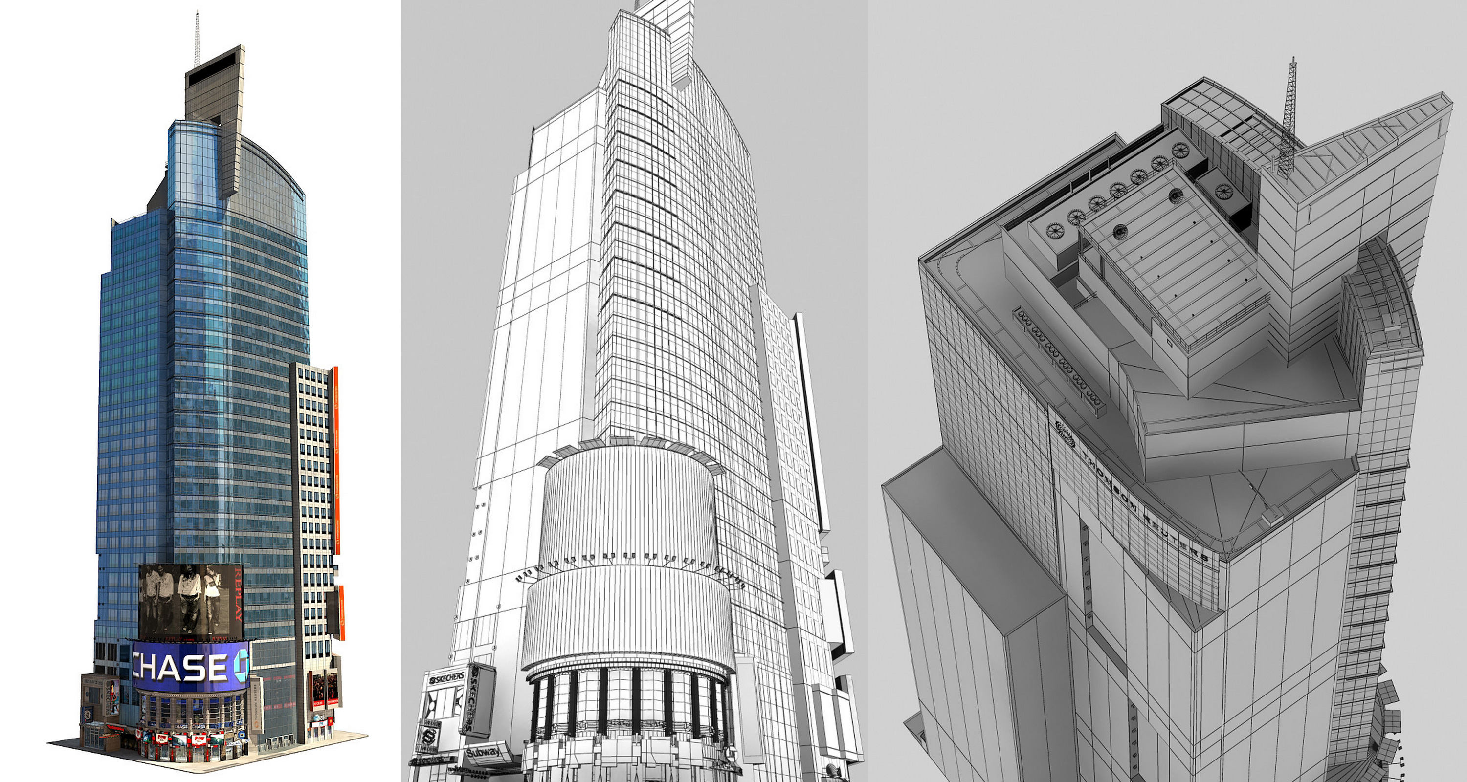
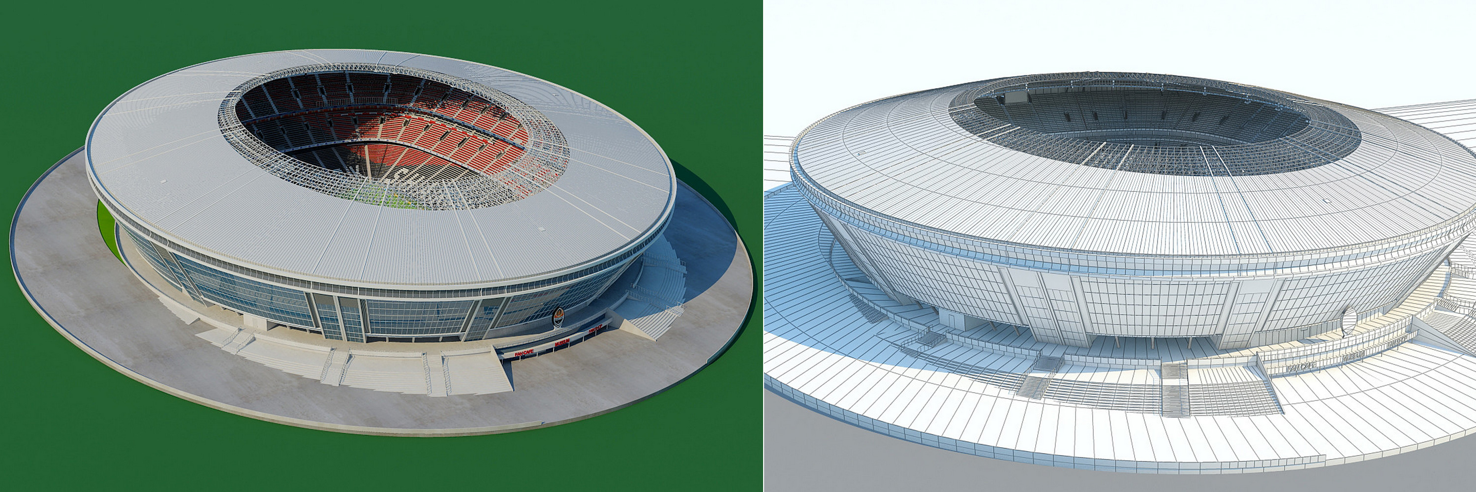
Architecture and Landmark models should be modeled and textured with enough detail to appear photo-real from 100 to 300 meters away, depending on the size of the structure.
[/vc_column_inner][vc_column_inner width=”1/2″]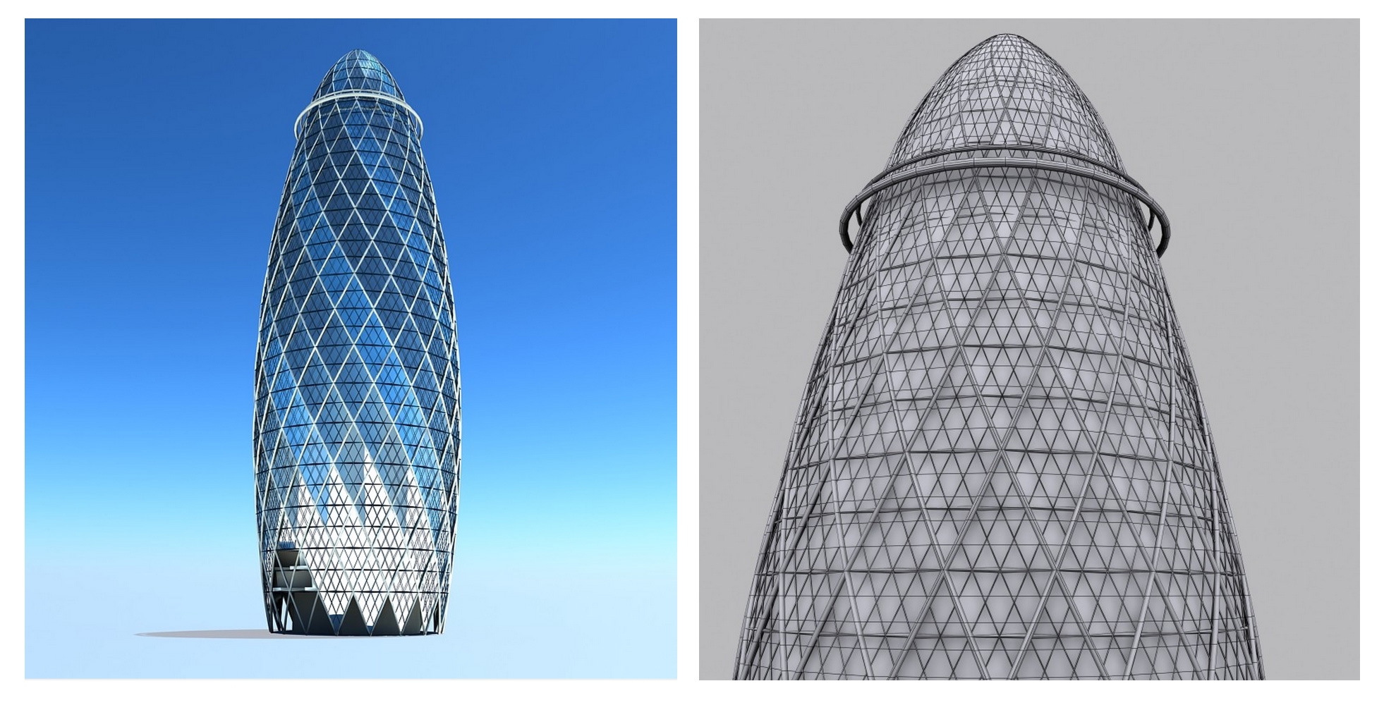
1.2Stylized
Stylized content means 3D models and scenes that are treated in a non-realistic style such a cartoons or graphics. Stylization can range from materials, such as an all white plastic apple, to geometry such as an iconic heart shape instead of a real human heart. Stylized objects must still have three dimensionality and accept lighting and shadows.
[/vc_column_inner][vc_column_inner width=”1/2″]

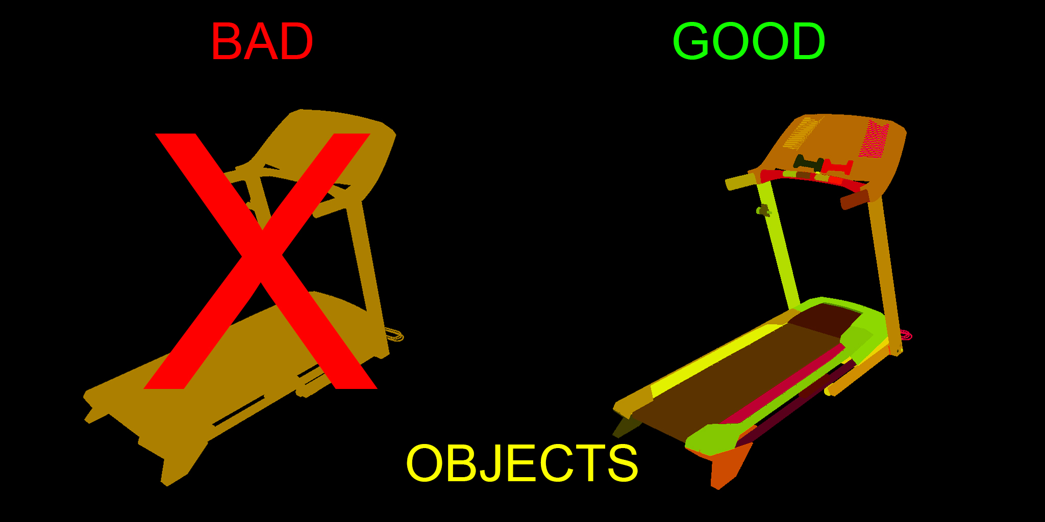
1.3Object Grouping
The model must consist of objects logically separated into individual pieces and individual materials with descriptive names. Proper organization and naming is key here. Do not attach or combine multiple objects into one big object on a complex model. Group selections of objects instead of attaching them. This keeps objects together while still being easily editable. Do not group the entire model as a single group. The Studio tool will group all your objects into a master group, Hero Object Group.
Anybody should be able to open your files, know exactly where everything is, and easily make adjustments. See Scene Organization and Best Practices for more information and examples.
[/vc_column_inner][vc_column_inner width=”1/2″]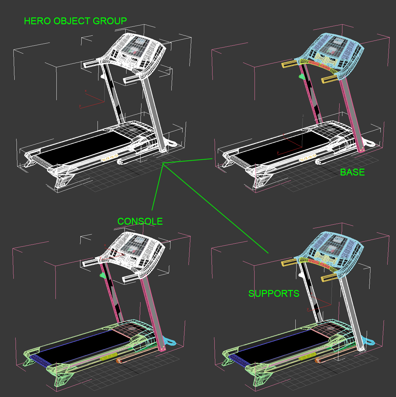

1.4Object/Group Pivots
Object pivots must be placed to allow for simple posing. Placement should be represent the function of how the real world object is rotated and posed.
[/vc_column_inner][vc_column_inner width=”1/2″]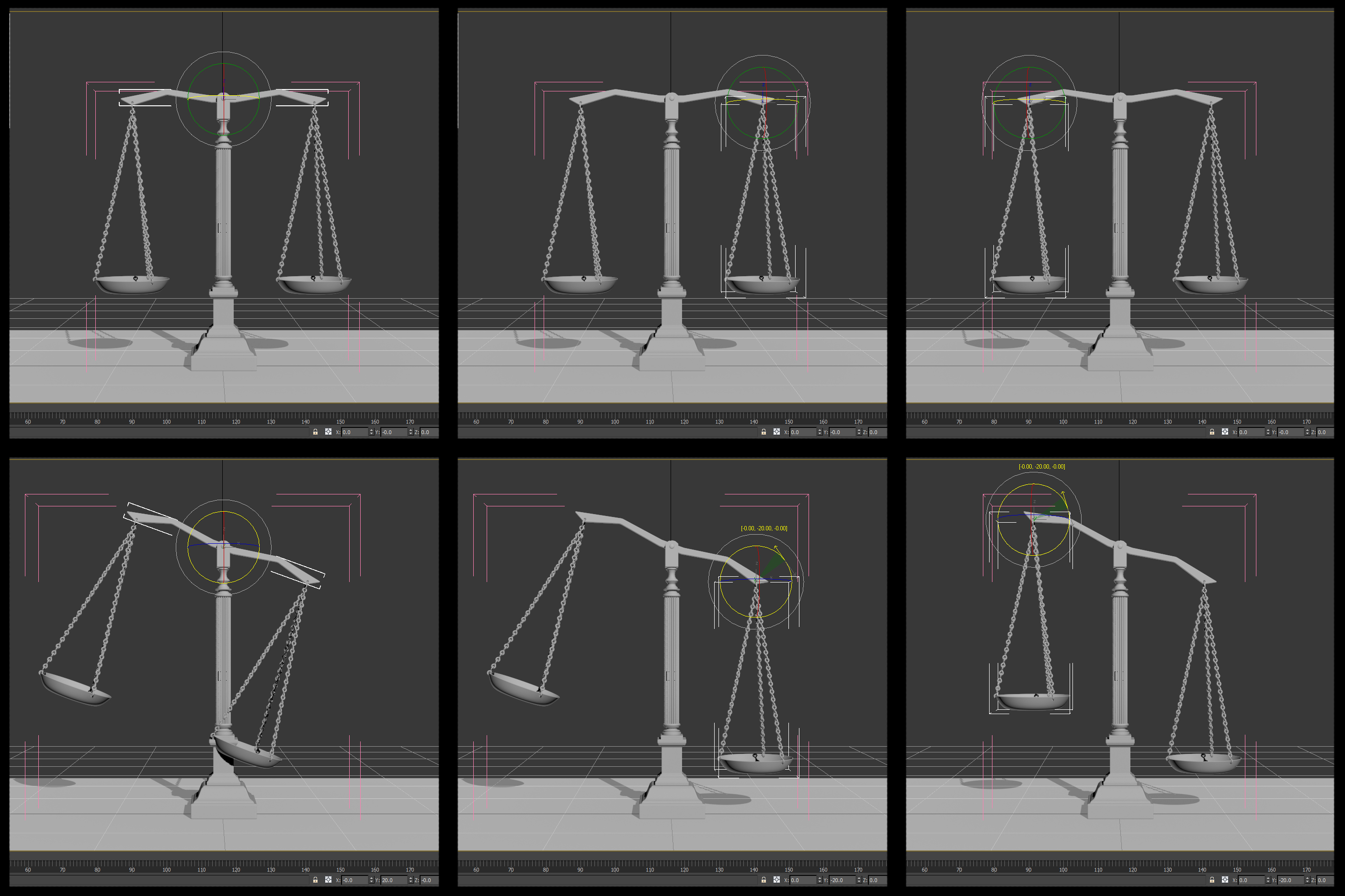
1.5Native Format
Acceptable max versions are 3ds Max 2011 and 3ds Max 2015. You can work in 3ds Max 2016 but you must back save to version 2015 or older.
NOTE: Back saving from newer versions of 3DS Max may cause issues if using newer features, such as modifiers, that do not exist in the older versions you are saving to.
1.6Test Rendering Format
Test renderings submitted for consideration must be in JPG format at 2048×2048 resolution, uploaded as individual files (not as part of a ZIP or RAR).
[/vc_column_inner][vc_column_inner width=”1/2″] [/vc_column_inner][/vc_row_inner][vc_row_inner][vc_column_inner width=”1/2″]1.7Hero Submission Format
Final upload for Hero submissions must be a ZIP or RAR file including the 3ds Max file, any textures, and the HTML result from the Inspection Script.
[/vc_column_inner][vc_column_inner width=”1/2″] [/vc_column_inner][/vc_row_inner][vc_row_inner][vc_column_inner width=”1/2″]1.8Scenes
Scenes are eligible for Hero certification only if a representative rendering fits completely within a frame.
Examples of eligible models: Airplane, Dining Room Set, Building, Street Scenes With All Elements Contained Within Frame
Examples of non-eligible models: Interiors, Street Scenes That Bleed Off The Frame
[/vc_column_inner][vc_column_inner width=”1/2″] [/vc_column_inner][/vc_row_inner][vc_row_inner][vc_column_inner width=”1/2″]1.9Model Variations
Model variations are specific to the job details. If the job has variants listed, each variant must be saved as a separate file.
NOTE: Job details may include special rendering instructions for submission.
1.10No Animation
Animated models are not eligible. However, you may submit posed versions of a model for certification, with each pose variation being a separate file. Poses will be specified in the job details.
[/vc_column_inner][vc_column_inner width=”1/2″] [/vc_column_inner][/vc_row_inner][vc_row_inner][vc_column_inner width=”1/2″]1.11External Plug-ins
Models that require external plug-ins other than V-Ray (such as hair/fur/cloth/particle simulation plug-ins, or other 3rd-party renderers) are not eligible for PixelSquid. UV unwrap programs and sculpting programs are usable, as long as it does not destructively affect the model.
[/vc_column_inner][vc_column_inner width=”1/2″] [/vc_column_inner][/vc_row_inner][vc_row_inner][vc_column_inner width=”1/2″]1.12No Branded Content
Models that require external plug-ins other than V-Ray (such as hair/fur/cloth/particle simulation plug-ins, or other 3rd-party renderers) are not eligible for PixelSquid. UV unwrap programs and sculpting programs are usable, as long as it does not destructively affect the model.
[/vc_column_inner][vc_column_inner width=”1/2″] [/vc_column_inner][/vc_row_inner]
2.0Standards for 3D Model Inspection
[vc_row_inner][vc_column_inner width=”1/2″]
2.1Model Setup
Models must be prepared using the Studio Tool. The script will prepare the scene with a stage, camera, lighting, and render settings so efforts can be focused on texturing. It is very important that you do not rename anything the script creates. The scene and lighting created by the Studio is specifically calibrated for Render Element contribution and correct Linear Workflow. For Spinner jobs the default camera lens option, 50mm, must be used unless otherwise specified in the job details. Use the most appropriate lighting option for the type of model in the scene.
[/vc_column_inner][vc_column_inner width=”1/2″] [/vc_column_inner][/vc_row_inner][vc_row_inner padding_top=”0px” padding_bottom=”0px” border=”none”][vc_column_inner width=”1/2″]2.2Geometry
2.2.1No isolated vertices
2.2.2No coincident edges
2.2.3No coincident/coplanar faces
2.2.4No Inverted Face Normals
No backfacing or inverted face normals. All normals should be pointing out towards the correct direction for rendering without errors. This is easily visible with backface culling on in object properties.
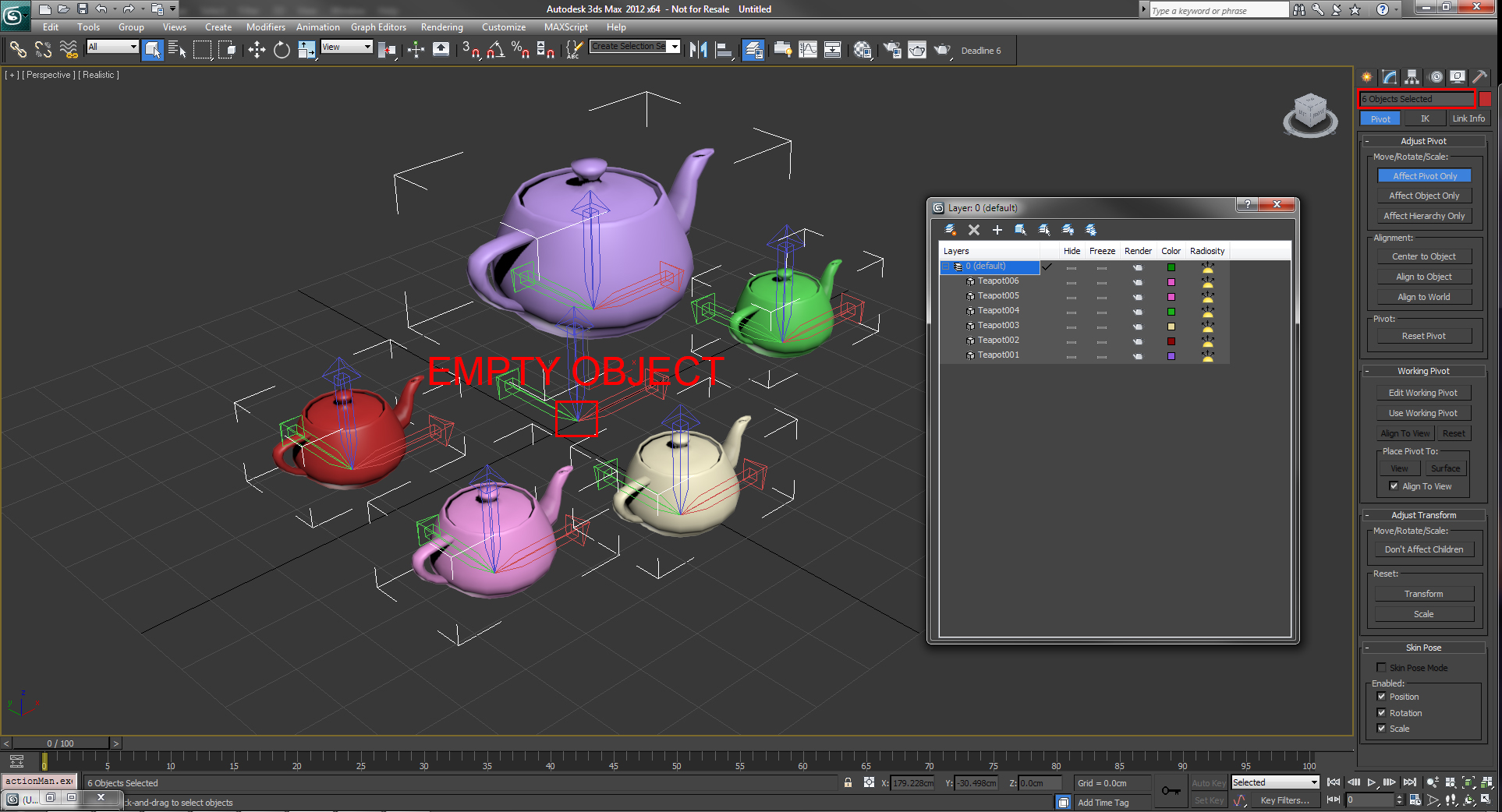
2.2.5No empty objects
All objects should have geometry or splines or be null/control helpers. Named object nodes that are empty bounding boxes are not allowed.
2.2.6No unwelded seams
Any two open edges on an individual object that meet or overlap in the same position must be welded.
2.2.7Instanced Object
Instancing can adversely affect normals in the scene, and can cause an object to have a non-100% scale at the object level. If used, original object should have all transforms reset before instancing
2.2.8Use of smoothing groups, crease values, and hard edges is not allowed.
[/vc_column_inner][vc_column_inner width=”1/2″]


2.3Topology
2.3.1Quads and triangles only
2.3.2Mostly quads
Mostly quads – The model must use quads as much as possible. A range of 10%-20% tris is sensible for most models, but some will call for a higher percentage to form sensible topology. Models are inspected manually to ensure a sensible quad/tri ratio is maintained.
2.3.3Edge flow
Must be as smooth and clean as possible for the shape of the model.
Use efficient box or planar modeling techniques when you begin your model. Avoid booleans and subdivision modifiers while you are still modeling the full object. This will help eliminate undesirable geometry that does not meet the Hero standard. If booleans are used, the verts and edges created must be cleaned up and optimized to correct edge flow and avoid Ngons. This is a notorious result of using booleans.
[/vc_column_inner][vc_column_inner width=”1/2″] [/vc_column_inner][/vc_row_inner][vc_row_inner][vc_column_inner width=”1/2″]2.3.3.1 Subdividable
Model is cleanly subdividable for higher detail and still retain shape of model.
NOTE: Architecture does not need to be subdividable geometry, but clean edge flow is still required.
2.3.3.2Holding/Support Edges
Holding/support edges present to retain shape after subdivision. This also applies to to 3D text.
NOTE: For Architecture No holding edges, chamfers, micro-bevels, etc. required.
2.3.3.3Small Object Exception
Exception for small, insignificant objects within the scene. Objects such as screws, bolts, rivets, wires, and other objects which are very small in comparison to the overall model size, does not have to meet all the Clean Edge Flow requirements for subdivision.
For Architecture and Landmark models it is ok to do difficult details with texture maps rather than modeling.
[/vc_column_inner][vc_column_inner width=”1/2″]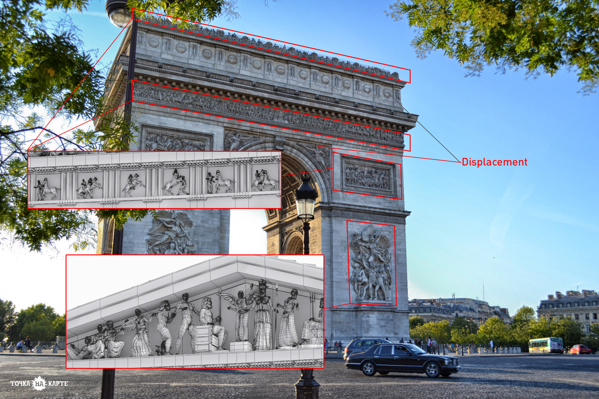

2.3.4Optimum mesh density
Optimum Poly count is minimum geometry necessary to retain shape and details of subdividable geometry. This takes into account results of smoothing modifiers. Overly dense geometry results in extra difficulty for editing, texturing, and rendering so it is best to keep geometry where it is needed. Most sculpting software evenly generates polygons regardless of surface detail which creates very dense geometry, even over flat areas. Use of sculpting programs is allowed but the geometry must be optimized where it can be.
2.3.4.1TurboSmooth /Meshsmooth
TurboSmooth/MeshSmooth in the modifier stack must be left uncollapsed. No more than one smoothing modifier in a stack. Do not exceed 2 iterations for subdividing. If more than 2 iterations feel needed the base mesh does not have enough detail modeled in.
WARNING: Collapsing a smoothing modifier to do this will produce undesirable geometry requiring geometry optimization. This can be done as part of the modeling process but cannot be collapsed on the mesh unedited. See above point.
2.3.4.2Displacement Modifiers
Displacement Modifiers maximum subdivision must not exceed 10 subdivision. Each subdivision iteration splits each triangle on the mesh times the subdivision amount. Displacement Modifiers using 3D Mapping or Subdivision methods subdivide the model similar to smoothing modifiers. These displacement methods must be used carefully with TurboSmooth/Meshsmooth modifiers.
WARNING: Combining both methods of smoothing creates excessive processing time causing slow rendering. If more geometry is needed to have a sufficient mesh to displace fine details add the required geometry to the detail areas of the base mesh. Increasing smoothing iterations will add geometry in areas it may not be needed.
2.3.4.3Collapse Modifiers
All modifiers other than subdivision modifiers (TurboSmooth, MeshSmooth, Displacement) must be collapsed. This includes geometry modifiers (Bend, Symmetry, Twist, etc…) and UV modifiers.
[/vc_column_inner][vc_column_inner width=”1/2″]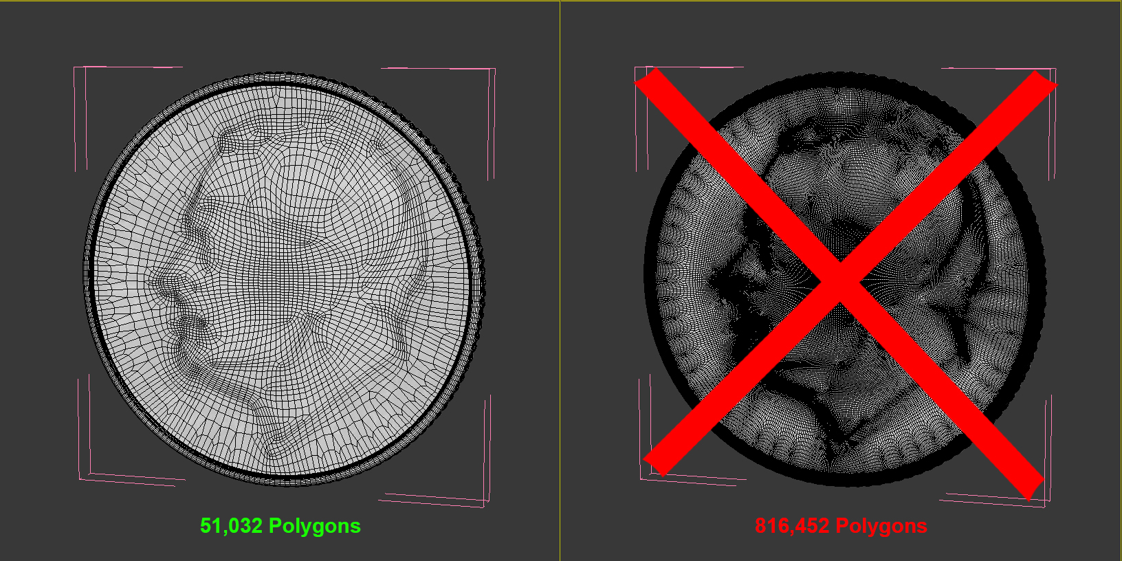
2.4Real-World Scale
2.4.1Real-world scale within 1%
If the model does not have an exact real-world counterpart (such as a human character or an unbranded car), the model must use the size/scale of comparable objects in real life.
2.4.2Exception for exceedingly large/small models
Models of objects that have a real-world scale that is too large to view as a whole (Planets, Land Masses) or would require magnification to see clearly (Water drop, Amoeba, Ant) are excepted from having real-world scale.
2.4.3System and Display Unit scale
System and Display Unit scale both must be set specifically in centimeters (no generic units).
[/vc_column_inner][vc_column_inner width=”1/2″] [/vc_column_inner][/vc_row_inner][vc_row_inner][vc_column_inner width=”1/2″]2.5Position and Orientation
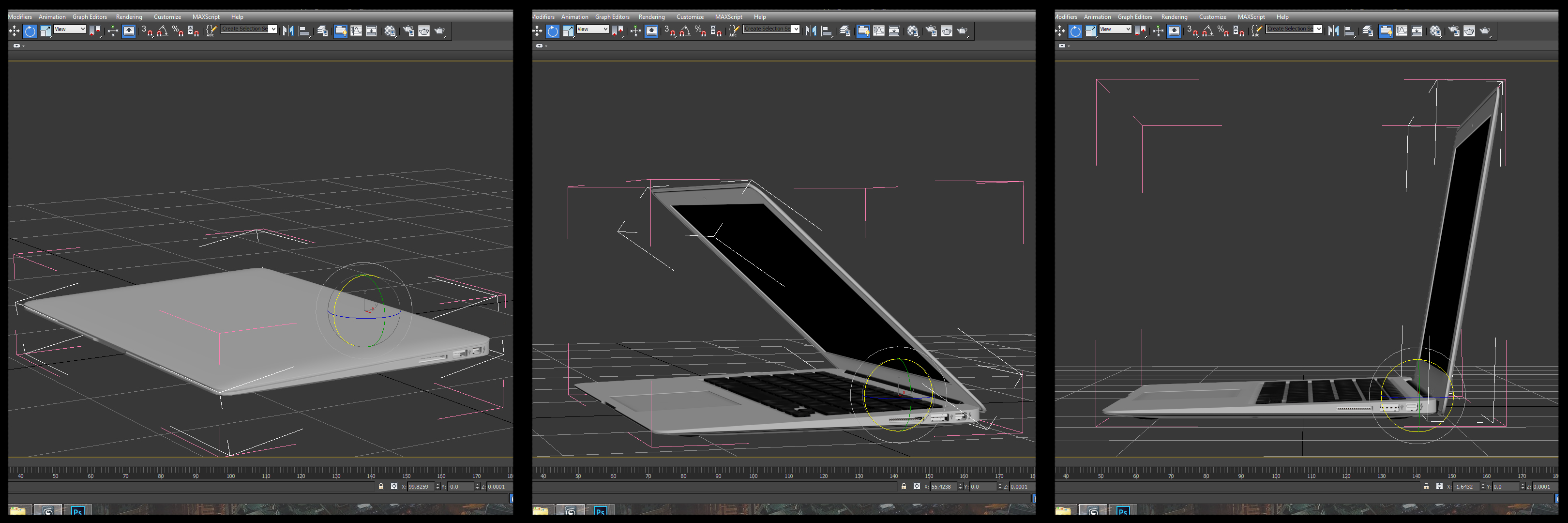
2.5.1Centered Origin
The model should be centered over the origin in X and Y axis, and the lowest Z point of the object sitting on the ground plane.
2.5.2Object Orientation
The model should be oriented to the orthographic positions as it would be considered in the real world. In other words, the model can’t be lying on its side, upside-down, or turned sideways when the file is opened. EXAMPLE: A car’s front end must be facing Front View and it’s roof facing Top View.
[/vc_column_inner][vc_column_inner width=”1/2″] [/vc_column_inner][/vc_row_inner][vc_row_inner][vc_column_inner width=”1/2″]2.6Transforms
2.6.1All objects at 100% scale at object level
If an object was scaled, scale transforms must be reset so object reads at 100% scale size
NOTE: Rigged models are an exception.
2.6.2All Transforms reset at object level
Position and rotation transforms must be reset to be 0 at final pose of model.
NOTE: Rigged models are an exception.
2.7Naming and Organization
2.7.1Short, descriptive and unique object names
Name all objects and textures in the scene. The names must be descriptive enough so that anyone could look at the layer editor and quickly select the desired object. Never leave anything as the default name such as Cylinder03, Object05, or Material #5. See Scene Organization and Best Practices for more detailed information.
Example: The Fuse object for the sample object “Classic bomb” should simply be named “Fuse” not “Classic_bomb_fuse”. Having “NameofModel_NameOfObject” as a prefix on every object in the scene can make names too long and throw off sorting when trying to quickly reference, select, or view the list of objects. You can clearly see the difference in the layer editor.
2.7.2All objects are in HeroObjectGroup
Grouping the object helps retain organization when exporting, or importing/merging the model with other scenes. All objects and “sub groups” of the model should be contained within the HeroObjectGroup generated by the Studio tool. The Studio tool will automatically group your model into this single master group when scene is prepared.
[/vc_column_inner][vc_column_inner width=”1/2″]
2.7.3Layer Organization
2.7.3.1All geometry objects and groups on one layer with same name as the model
See Scene Organization and Best Practices for more detailed information.
2.7.3.2Descriptive Layer Naming
Any other types of objects organized using layers are named with simple and descriptive, easy-to-scan names.
Use layers logically to organize groups of items in the scene, lights, stage, bounce cards, and other necessary scene elements.
[/vc_column_inner][vc_column_inner width=”1/2″] [/vc_column_inner][/vc_row_inner][vc_row_inner][vc_column_inner width=”1/2″]2.7.4Models must consist of logically separated objects and materials.
[/vc_column_inner][vc_column_inner width=”1/2″]
2.8Textures and Materials
2.8.1All materials used must be a V-Ray material type
Objects do not have to have texture maps, but each one must have a V-Ray material type applied. This means base and submaterials also.
2.8.2No Multi/Sub-Object materials
Multi/Subobject materials make editing and navigating materials on a model extremely difficult. The ability to select by material is taken away. Which materials are applied to specific subobjects or faces can not easily be determined.
2.8.3Texture files and nodes named simple and descriptive, easy-to-scan names
See Scene Organization and Best Practices for more detailed information.
2.8.4Model in Calibrated Light Rig
The model must be rendered in a Calibrated Light Rig provided in the Studio Tool. This ensures consistent Texture, Material, and Shader quality.
2.8.5No mapped texture paths
Any texture paths must be stripped from model and be relative for submission.
2.8.6All texture maps must be saved as lossless or uncompressed formats such as PNG, EXR, and TGA. Excludes TIF files due to compatibility issues.
2.8.7All bitmap textures are square resolution
Texture maps must be square resolution, meaning height and width of a texture maps are the same. Texture maps size should be determined by amount of detail needed. If using a texture map for a solid color swatch it does not need to be 2048×2048 pixels. Being conscious of the texture size helps optimize render times and file transfers for submission. If a smaller resolution can be used with no noticeable difference on the render, do so. Try to keep map usage and size as efficient as possible.
2.8.8Procedural textures are permitted
2.8.9Gamma Correction
Gamma correction must be done according to linear workflow. Below you will see the settings that are generated by the stage setup script.
It is important your scene be setup to work in a linear workflow from the start. This will provide more consistent results when texturing and lighting. To better understand linear workflow and its importance see Linear Workflow.
[/vc_column_inner][vc_column_inner width=”1/2″] [/vc_column_inner][/vc_row_inner][vc_row_inner][vc_column_inner width=”1/2″]
2.8.10Glass Objects Alpha
For any material where the Refract color is not 0,0,0 “Affect channels” on Refraction must be set to “Color+alpha”. Most commonly, this applies to glass or transparent plastic material types.
[/vc_column_inner][vc_column_inner width=”1/2″]
2.9UVs
2.9.1All parts of the models must have unwrapped, non-overlapping UVs
Individually small objects that are part of a much larger model being cloned may have overlapping UVs. Small objects such as fasteners (screws, bolts, nuts), foliage (leaves, flower petals), or details like windows on an building exteriors or a cruise ship could be allowed if texture quality meets requirements. Subject to QA’s discretion.
2.9.1.1Multiple UVs Per Texture
The model can use more than one texture, in which case there will be more than one set of unwrapped, non-overlapping UVs per texture
2.9.1.2Using Materials
If a material does not have any textures maps, any objects using that material still must have unwrapped, non-overlapping UVs.
The final packed UVs should have minimal negative/wasted texture space. UV map should be laid out to maximize pixel density where it counts. If an item is small on the model, then it should be small on the UV sheet.
2.9.2No obvious texture stretching on model
2.9.3Texture Seams not visible
2.9.4UVs must be in 0-1 texture space
You can easily tell if your UVs are in the 0-1 texture space by applying an Unwrap UVW modifier to selected object(s) and looking at the Edit UVW dialog. The 0-1 texture space is the central square with the heavy line around it. Your UVs cannot go outside this area.
[/vc_column_inner][vc_column_inner width=”1/2″] [/vc_column_inner][/vc_row_inner][vc_row_inner][vc_column_inner width=”1/2″]2.10Rigging
2.10.1Transforms must be frozen/reset unless model is animated
2.10.2Hierarchy objects must be uniquely and appropriately named
2.10.3Rig must function as expected – Rig must perform simple deformations
2.10.4Custom rig must include instructions
A Readme, PDF document, or other documentation on how to use the rig. Rigs that use Biped or CAT are not required to have a read me unless there are custom controls.
2.10.5Rig has No Animation or Keyframes
[/vc_column_inner][vc_column_inner width=”1/2″] [/vc_column_inner][/vc_row_inner][vc_row_inner][vc_column_inner width=”1/2″]2.11Lights
2.11.1Light Layer
Lights must remain on their own layer created by the Studio Tool.
2.11.2No Extra Lights
The scene must not include lights other than those provided.
[/vc_column_inner][vc_column_inner width=”1/2″] [/vc_column_inner][/vc_row_inner][vc_row_inner][vc_column_inner width=”1/2″]2.13Final Scene Setup
2.13.1All render elements contribute to the final image
After rendering in V-Ray Frame Buffer. All render elements contain information from the render. No layer should be completely black. The only exception would be if there are no materials with refraction then the Refraction layer will be black.
2.13.2High Quality Settings
The scene must be set to High Quality Settings using the Studio Tool before submission.
2.13.3Render Setup dialog settings
Render Output, Save File: unchecked
No render path specified
Time Output: Single
Area to Render: View
View:RenderCamera
In the VRay Framebuffer, Render Region: Off